
SOURCING SUPPORT
Need Help With TMDS181IRGZR?
Contact our sourcing team for current stock, batch information, lead time, technical documents, alternative parts and volume pricing.
Stock & Batch Verification
Confirm available quantity, date code and delivery schedule.
Alternative Part Sourcing
Request compatible or replacement parts when stock is limited.
Quality & Packaging Check
Confirm product condition, packaging type and shipment protection before dispatch.
-
Supplier Verification
Supplier review and component quality inspection support.
-
Technical Documents
Datasheet and specification confirmation for engineers.
-
One-Stop BOM Sourcing
Multi-part procurement and shortage sourcing assistance.
Texas Instruments
RFQ AVAILABLE
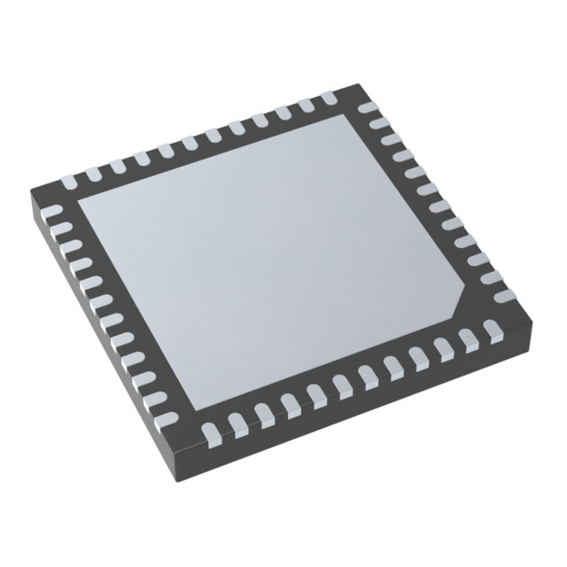
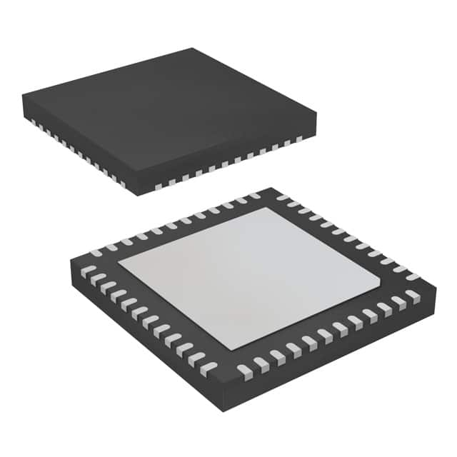
TMDS181IRGZR
IC INTERFACE SPECIALIZED 48VQFN
- Part Number
- TMDS181IRGZR
- Manufacturer
- Texas Instruments
- Category
- Specialized
- Package
- 48-VFQFN Exposed Pad
- Datasheet:
- TMDS181IRGZR.pdf
- Description
- IC INTERFACE SPECIALIZED 48VQFN
Select Quantity
Stock:
783
| Qty. | Unit Price | Ext. Price |
| 2500+ | $2.43424 | $6085.60 |