
1. What Is a Display Driver IC? – The "Brain" of the Display Panel
A display driver IC (often abbreviated as DDIC) is the core component that enables a display panel to render images. It integrates resistors, regulators, comparators, and power transistors to deliver the necessary drive signals and current to the panel. Think of it as the "translator" that converts the digital image data coming from the host processor (e.g., a smartphone SoC or a GPU) into the analog voltages and currents that individual pixels understand.
In a typical display system, the complete drive solution comprises several chips working in harmony: the source driver, gate driver, timing controller (TCON), and power management IC. Each plays a distinct role, and together they ensure that every pixel lights up with the correct colour and intensity at the right moment.
2. Classification of Display Driver ICs
Display driver ICs can be categorised in two main ways: by the underlying display technology they drive, and by their driving method.
2.1 By Display Technology
| Type | Target Panel | Typical Applications |
|---|---|---|
| LCD DDIC | TFT‑LCD, STN‑LCD | TVs, monitors, laptops, industrial displays |
| OLED DDIC | AMOLED, PMOLED | Smartphones, smartwatches, premium TVs |
| TDDI (Touch + Display) | LCD with integrated touch | Smartphones, tablets |
| Mini/Micro LED DDIC | Mini LED, Micro LED | High‑end displays, large‑format screens |
Among these, TDDI has gained significant traction in the smartphone market because it combines the touch controller and display driver into a single chip, reducing PCB area and BOM cost.
2.2 By Driving Method
- Static drive: Used for simple segment displays (e.g., calculators, digital clocks). Each pixel is driven independently; simple but pin‑count becomes prohibitive for high‑resolution panels.
-
Dynamic (matrix) drive: Employed for dot‑matrix displays. By time‑multiplexing row and column signals, the number of required pins is drastically reduced. Dynamic drive further splits into:
- Passive matrix (PM): Used in TN and STN LCDs. Low cost but suffers from cross‑talk at higher densities.
- Active matrix (AM): Used in TFT‑LCDs. Each pixel has its own thin‑film transistor (TFT) switch, delivering superior image quality and faster response.
3. Working Principle of LCD Driver ICs
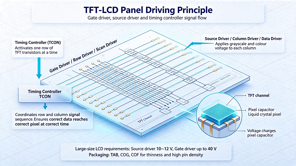
To understand how an LCD driver works, you need to be familiar with the panel's scanning architecture. LCDs use a column‑by‑column scanning approach - one column is scanned at a time, from top to bottom.
- Gate driver (row driver / scan driver): Connected to the gate lines of the TFTs. It turns on one row of transistors at a time.
- Source driver (column driver / data driver): While a row is active, the source driver applies the appropriate voltage (corresponding to grayscale and colour) to each column. These voltages pass through the TFT channels to charge the pixel capacitors.
- Timing controller (TCON): Orchestrates the entire process - it decides the sequence and timing of the row and column signals, ensuring that the correct data reaches the correct pixel at the correct time.
For large‑size LCD panels, the driver ICs must handle high voltages (source drivers typically operate at 10–12 V, while gate drivers can go up to 40 V), run at high frequencies (to keep up with increasing resolutions), and use specialised packaging such as TAB, COG, or COF to achieve the required thinness and pin density.
4. LED Driver ICs and LED Controller ICs – What's the Difference?
While the name may sound similar, an LED driver IC and an LED controller IC serve different purposes.
- LED driver IC: Integrates the power MOSFET(s) internally. It can directly drive an LED load with a regulated constant current. It is a self‑contained power stage.
- LED controller IC: Does not include the power MOSFET. It provides control signals and driving logic, but requires an external power transistor to handle the current. This gives designers more flexibility in choosing the FET size and type for high‑power applications.
In LED backlighting or LED display applications, the led driver ic receives display data, internally generates PWM signals and current profiles, and outputs a PWM‑modulated current that determines brightness, grayscale, and refresh rate. For high‑performance systems, you may also encounter led controller ic solutions where the external MOSFET allows for higher current handling and better thermal management.
5. Display Controller vs. Display Driver – Roles and Boundaries
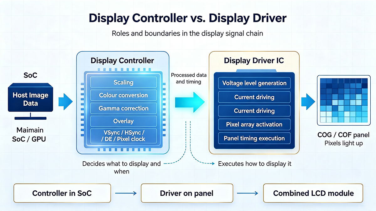
One of the most common points of confusion is the distinction between a display controller and a display driver. They are complementary but not interchangeable:
- Display controller: Receives image data from the host, performs processing (scaling, colour conversion, gamma correction, overlay), and generates the timing signals (VSync, HSync, DE) and pixel clock. It decides what to display and when.
- Display driver IC: Takes the processed data and timing from the controller and converts it into the actual voltage/current levels required to drive the panel. It executes how to display it.
In many modern systems, the display controller is integrated into the main SoC (e.g., the GPU block of a smartphone processor), while the display driver ic is a separate chip located on the display panel itself (COG or COF). For simple LCD modules, the lcd controller may be integrated into the module along with the driver, forming a complete "display driver + controller" solution.
6. The Complete Ecosystem of All LCD Panel Drivers
When we talk about all lcd panel drivers, we refer to the entire chipset that makes a modern LCD panel work. This ecosystem typically includes:
- Source driver – converts digital pixel data into the analog voltage that drives each column.
- Gate driver – scans the rows sequentially, turning TFTs on and off.
- Timing controller (TCON) – synchronises the source and gate drivers.
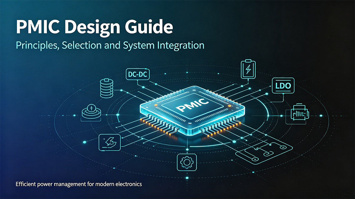
- Power management IC (PMIC) – generates the multiple supply rails required (AVDD, VGH, VGL, VCOM, etc.).
- Gamma reference IC – provides the reference voltage ladder for grayscale accuracy.
Depending on the panel substrate technology, the drivers may be optimised for a‑Si (amorphous silicon), IGZO, or LTPS backplanes. Each has different voltage and drive current requirements, so it is important to select drivers that are matched to the panel's technology.
7. Selection Guidelines for Display Driver ICs
Choosing the right display driver ic for your project involves evaluating several key parameters:
| Parameter | Description | Selection Tips |
|---|---|---|
| Resolution support | Maximum panel resolution the IC can drive | Must be ≥ your target resolution |
| Interface type | RGB, MIPI‑DSI, LVDS, SPI, I²C, etc. | Must match the host processor's available interface |
| Output voltage range | Voltage swing that the driver can produce | Must comply with the panel's VCOM, VGH, VGL requirements |
| Number of channels | Source/gate output count | Must cover the panel's columns/rows |
| Power consumption | Active and standby power | Portable devices need low‑power options |
| Package type | COG, COF, TAB, etc. | Must be compatible with panel bonding process |
A typical selection workflow:
- Define the panel type (LCD or OLED), resolution, and size.
- Identify the host interface (e.g., MIPI‑DSI for smartphones).
- Estimate power budget and thermal constraints.
- Consider integration level - would a TDDI chip simplify your design?
- Check supply chain availability and cost.
8. PCB Layout and System Design Essentials
Even the best display driver ic will perform poorly if the PCB layout is suboptimal. Here are key guidelines for laying out the driver and its associated circuitry:
- Keep signal paths short: Minimise the trace length between the driver and the panel connector to reduce signal attenuation and EMI.
- Match impedances: For high‑speed interfaces like MIPI or LVDS, maintain controlled differential impedance (typically 100 Ω differential).
- Decouple power rails: Place ceramic capacitors close to each power pin of the driver to suppress high‑frequency noise.
- Provide a solid ground plane: A continuous reference plane under the driver reduces ground bounce and improves signal integrity.
- Manage heat: High‑resolution, large‑panel drivers can dissipate significant power. Use thermal vias and copper pours to conduct heat away from the IC.
Common issues that arise from poor layout include display flicker (caused by power supply noise), vertical/horizontal lines (due to open or shorted driver channels), colour inaccuracies (from poor gamma reference routing), and EMI failures (from unsuppressed high‑speed lines).
9. Frequently Asked Questions (FAQ)
A display driver IC converts signals to panel‑specific voltage/current levels to drive pixels, while a display controller handles image data processing, timing generation, and signal distribution. Think of the controller as the commander and the driver as the executor.
No. LCD driver ICs output voltage signals to control liquid crystal alignment, whereas LED driver ICs provide constant current sources to drive LEDs. Their operating principles and output characteristics are fundamentally different.
TDDI (Touch and Display Driver Integration) combines touchscreen controller and display driver functions into a single IC. It is widely used in smartphone LCD panels to save PCB space and reduce overall system cost.
Common symptoms include no display, abnormal patterns (snow, streaks), colour distortion, or unresponsive touch (on TDDI solutions). You can diagnose by measuring key pin voltages, checking timing signals, or replacing the suspect IC.
The main forms are TAB (Tape Automated Bonding), COF (Chip on Film), and COG (Chip on Glass). COG is the thinnest and is common in mobile devices; COF is suitable for large, high‑resolution panels.
10. Industry Trends and Outlook
The display driver IC market is undergoing rapid transformation. According to industry forecasts, the global DDIC market is expected to reach $21.3 billion by 2026, growing at a CAGR of 6.5%. Key trends driving this growth include:
- Higher resolution: Drivers that support 4K, 8K, and beyond are becoming mainstream.
- Ultra‑low power: Wearables and IoT devices demand ever‑lower power consumption.
- Increasing integration: TDDI and other combo chips are gaining share, reducing the number of external components.
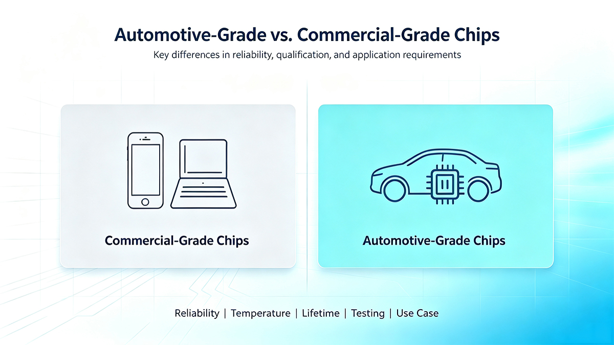
- Automotive displays: The rise of electric and connected vehicles creates strong demand for automotive‑grade DDICs with wide temperature ranges and high reliability.
- New display technologies: Mini‑LED and Micro‑LED panels require new driver architectures that can handle thousands of local dimming zones.
- Localisation of supply chain: Chinese fabless companies are increasing their share in the TV DDIC market, offering cost‑competitive alternatives.
11. Conclusion
Display driver ICs are the unsung heroes behind every modern screen - from the tiny OLED on a smartwatch to the massive 8K television on your wall. Understanding the distinctions between lcd driver, led driver ic, and display controller, and knowing how to select and deploy the right display driver ic for your application, is essential for any display system designer.
By following best practices in driver selection, PCB layout, and thermal management, and by keeping up with the latest industry trends, engineers can create displays that deliver stunning image quality, high reliability, and optimal power efficiency. Whether you are building a consumer device, an automotive infotainment system, or an industrial control panel, the right driver IC will make all the difference.