
1. What Is a Precision Resistor?
A precision resistor is a resistive component characterized by tight tolerance (typically ±1% or better), low temperature coefficient of resistance (TCR), and excellent long-term stability[reference:1]. While standard resistors may have tolerances of ±5% or ±10% and TCR values of ±200 ppm/°C or higher, precision resistors are designed to maintain their specified resistance value across temperature variations, power fluctuations, and extended operating periods.
Precision resistors are distinguished from power resistors not by construction alone but by design emphasis[reference:2]. Precision resistors prioritize accuracy and stability over power dissipation capability, and they generally have restricted operating temperature limits and power dissipation ratings. Power resistors, by contrast, emphasize heat dissipation and often have extended temperature limits-though some power resistors can also offer tight tolerances.
The selection of a precision resistor involves more than simply choosing a resistance value. Engineers must evaluate tolerance, TCR, power rating, load-life stability, noise, and voltage coefficient to ensure the component functions correctly across all operating extremes[reference:3][reference:4].
2. Core Performance Indicators
Five key parameters define the performance level of a precision resistor. Understanding these metrics is essential for making informed selection decisions.
2.1. Resistance Tolerance
Tolerance specifies the maximum deviation between the actual resistance and the nominal value, expressed as a percentage. Common tolerance grades for precision resistors include:
- Ultra-precision: ±0.01% to ±0.1% (typically thin film or metal foil)[reference:5]
- Precision: ±0.1% to ±0.5% (typically thin film)[reference:6]
- Semi-precision: ±1%[reference:7]
- Standard: ±2% to ±5% (thick film or carbon film)[reference:8]
Tolerance directly affects the absolute accuracy of voltage dividers, gain networks, and reference circuits. In differential amplifier applications, even small tolerance mismatches between paired resistors can significantly degrade common-mode rejection ratio (CMRR)[reference:9].
2.2. Temperature Coefficient of Resistance (TCR)
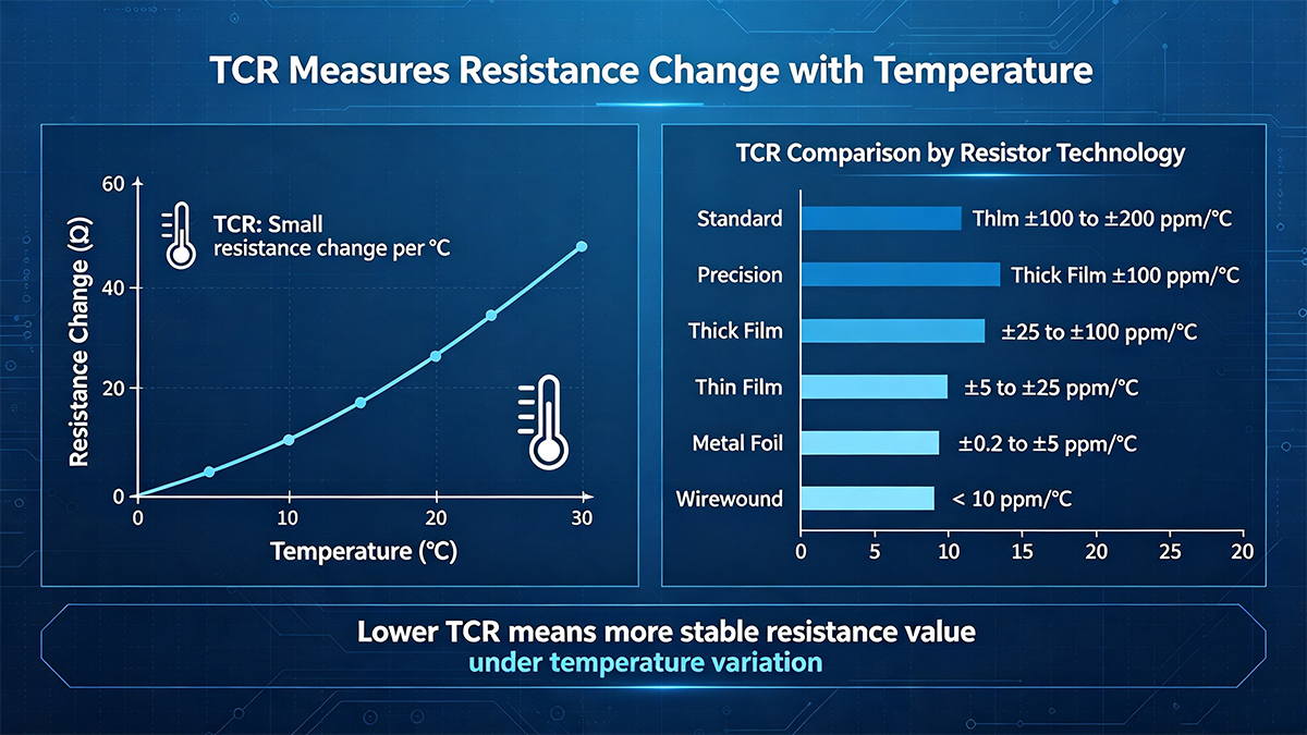
TCR measures how much a resistor's value changes with temperature, expressed in parts per million per degree Celsius (ppm/°C)[reference:10]. A resistor with ±100 ppm/°C TCR and a nominal value of 1,000 Ω will change by ±0.1 Ω for every 1°C temperature change[reference:11].
For precision applications, lower TCR is always preferable[reference:12]:
- Standard thick film: ±100 to ±200 ppm/°C[reference:13]
- Precision thick film: ±25 to ±100 ppm/°C[reference:14]
- Thin film: ±5 to ±25 ppm/°C[reference:15][reference:16]
- Metal foil: As low as ±0.2 to ±5 ppm/°C[reference:17]
- Wirewound: < 10 ppm/°C[reference:18]
For high-precision instruments such as medical equipment, ultra-low TCR thin-film resistors with TCR ≤ 5 ppm/°C are often required[reference:19].
2.3. Power Rating and Derating
The power rating specifies the maximum continuous power the resistor can dissipate without exceeding its maximum temperature. In precision applications, it is advisable to derate the resistor to 60% or less of its rated power to minimize self-heating effects. Even 100 mW in a small SMD resistor can cause a temperature rise of 20°C to 60°C, depending on PCB layout and copper area[reference:20].
2.4. Load-Life Stability
Load-life stability describes the resistance change after prolonged operation under load. This parameter reflects long-term reliability and is particularly important in industrial and medical applications where calibration intervals are extended[reference:21].
2.5. Noise
Excess noise-generated by the granular structure of the resistive material-can be a critical factor in low-level signal applications. Thin-film and metal foil resistors exhibit significantly lower noise than thick-film or carbon composition types[reference:22].
3. Main Resistor Types and Applicable Scenarios
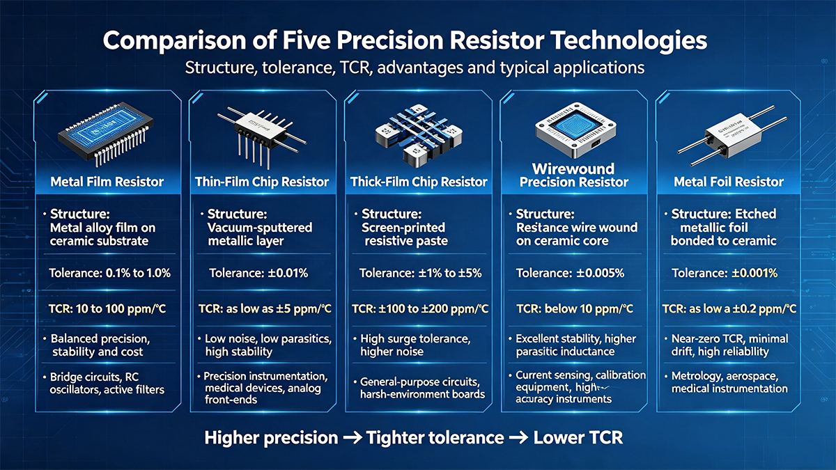
Different manufacturing processes yield distinct electrical characteristics, making each resistor technology suitable for specific applications[reference:23].
3.1. Metal Film Resistor
Metal film resistors are the workhorse of precision analog design[reference:24]. They are manufactured by depositing a thin layer of metal alloy (typically Nichrome, tin oxide, or tantalum nitride) onto a ceramic substrate[reference:25][reference:26]. Initial accuracies range from 0.1% to 1.0%, with TCR between 10 and 100 ppm/°C[reference:27][reference:28]. They offer a balanced combination of precision, stability, and cost, making them suitable for bridge circuits, RC oscillators, active filters, and general-purpose precision applications[reference:29].
3.2. Thin-Film Chip Resistor
Thin-film resistors are manufactured using vacuum sputtering to deposit a uniform metallic layer (typically 0.1 μm thick) onto a ceramic or silicon substrate[reference:30]. The homogeneous metal structure provides extremely low noise, minimal parasitic inductance, and excellent stability over temperature and time[reference:31]. Tolerances can reach ±0.01%, with TCR as low as ±5 ppm/°C[reference:32][reference:33]. They are the preferred choice for precision instrumentation, medical devices, and high-accuracy analog front-ends[reference:34]. However, their ultra-thin construction makes them more vulnerable to ESD and chemical contamination[reference:35].
3.3. Thick-Film Chip Resistor
Thick-film resistors are manufactured by screen-printing a resistive paste (metal oxides mixed with glass frit) onto a ceramic substrate and firing at high temperatures[reference:36]. The resulting film is 10 to 50 μm thick[reference:37]. Thick-film resistors excel in harsh environments and can handle high current surges[reference:38]. However, their granular structure results in higher noise and makes it difficult to achieve tight tolerances-typically ±1% to ±5%, with TCR of ±100 to ±200 ppm/°C[reference:39]. They are widely used in general-purpose circuits where extreme precision is not required.
3.4. Wirewound Precision Resistor
Wirewound resistors are constructed by winding a resistance wire (typically a special alloy) around a ceramic or glass core[reference:40]. They offer exceptional accuracy and stability-tolerances as tight as ±0.005% and TCR below 10 ppm/°C[reference:41][reference:42][reference:43]. However, their wire-wound structure introduces significant parasitic inductance (many μH), making them unsuitable for high-frequency applications[reference:44]. They are used in demanding applications such as precision current sensing, calibration equipment, and high-accuracy instrumentation[reference:45].
3.5. Metal Foil Resistor
Bulk Metal® Foil resistors represent the pinnacle of precision resistor technology[reference:46]. They are manufactured by bonding a metallic foil to a ceramic substrate and photochemically etching a resistance pattern. They deliver near-zero TCR, minimal drift, and superior immunity to ESD and thermal cycling[reference:47]. Tolerances can reach ±0.001%, with TCR as low as ±0.2 ppm/°C[reference:48]. They are the preferred choice for metrology, aerospace, medical instrumentation, and other high-reliability applications where absolute accuracy is non-negotiable[reference:49]. However, they are significantly more expensive than thin-film alternatives[reference:50].
4. Comparison: Precision Resistor Technologies
| Technology | Tolerance | TCR (ppm/°C) | Noise | Inductance | Cost | Best Use Case |
|---|---|---|---|---|---|---|
| Metal Film | 0.1% ~ 1.0% | 10 ~ 100 | Low | Low | Moderate | Bridge circuits, filters, general precision |
| Thin Film | 0.01% ~ 0.1% | 5 ~ 25 | Very Low | Very Low | High | Instrumentation, medical, high-accuracy AFE |
| Thick Film | 1% ~ 5% | 100 ~ 200 | High | Low | Very Low | General-purpose, power electronics |
| Wirewound | 0.005% ~ 0.1% | < 10 | Very Low | High (many µH) | High | Precision current sensing, calibration |
| Metal Foil | 0.001% ~ 0.01% | 0.2 ~ 5 | Extremely Low | Very Low | Very High | Metrology, aerospace, high-reliability |
This comparison illustrates the fundamental trade-offs in precision resistor selection[reference:51]. Thin-film and foil technologies offer superior precision and stability at higher cost, while thick-film provides a cost-effective solution for less demanding applications[reference:52].
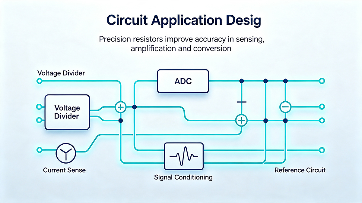
5. Circuit Application Design
5.1. Voltage Divider Circuits
In precision voltage divider applications, the ratio accuracy of the two resistors is more important than absolute accuracy. Two resistors with 1% individual tolerance can produce a divider ratio error of up to 2%, while a matched resistor pair with 0.1% ratio tolerance provides far better performance. For applications requiring high accuracy, matched resistor networks or resistor pairs from the same batch should be used[reference:53].
When selecting divider resistors, consider both tolerance and TCR matching. Even if two resistors have the same nominal value, mismatched TCR will cause the divider ratio to drift with temperature[reference:54]. Precision matched thin-film resistor networks offer exceptional initial ratiometric matching and long-term stability across time and temperature[reference:55].
5.2. Operational Amplifier Feedback Networks
In operational amplifier circuits, the feedback resistor (Rf) and input resistor (Rin) determine the gain. For precision gain applications, both resistors should be selected with tight tolerance and matched TCR[reference:56]. In instrumentation amplifiers, resistor matching is even more critical-CMRR is directly proportional to the precision of the resistor ratios[reference:57][reference:58].
For inverting amplifier configurations, using identical series resistors for the inverting and non-inverting terminals helps balance input bias current errors. High-value resistors (> 100 kΩ) can degrade phase margin and introduce additional noise, so the lowest practical resistance values should be used[reference:59].
5.3. Current Sensing Applications
Precision current sensing requires resistors with low TCR, low resistance values, and high power handling capability. For shunt resistors below 1 Ω, metal foil or specialized alloy resistors are typically required because only alloy materials can maintain stability under high current conditions[reference:60]. Four-terminal (Kelvin) connections are recommended for precision current sensing to eliminate the effects of lead and trace resistance[reference:61].
When selecting a current-sense resistor, consider the following: TCR (as low as ±5 ppm/°C for foil types)[reference:62], power derating (allow margin for self-heating), and package size (larger packages dissipate heat more effectively). Precision current-sense resistors can replace Hall-effect current sensors in many applications, offering significant cost advantages[reference:63].
6. PCB Layout Guidelines for Precision Resistors
Proper PCB layout is essential for preserving the accuracy of precision resistors[reference:64]. Even a 0.1% resistor can exhibit significant errors if layout practices introduce thermal gradients or stress.
- Symmetrical layout for matched pairs: Place matched resistors side by side to ensure consistent ambient temperature and synchronous resistance drift. For differential amplifier circuits, matching the physical orientation of paired resistors minimizes thermal gradient effects.
- Avoid thermal gradients: Orient resistor axes perpendicular to the dominant airflow direction to minimize temperature differences between the two ends of the resistor[reference:65]. Standing a resistor on end creates thermal gradients and should be avoided[reference:66].
- Separate from heat sources: Keep precision resistors away from power components, voltage regulators, and high-current traces that generate heat[reference:67].
- Proper pad design: Use moderate pad sizes-large copper areas increase thermal mass and slow response, while undersized pads can create mechanical stress. Avoid placing copper traces directly under the resistor body[reference:68].
- Kelvin connections for current sensing: For low-value shunt resistors, use four-terminal (Kelvin) connections to eliminate the effects of trace resistance and solder joint resistance[reference:69].
- Analog ground separation: Connect sampling resistor ground terminals to a clean analog ground to eliminate ground loop voltage errors.
7. Common Failures and Abnormal Phenomena
Most precision resistor failures can be traced to thermal effects, mechanical stress, or incorrect selection. Below are typical issues and their root causes:
- Resistance drift from self-heating: Operating a resistor near its power rating causes significant temperature rise, which shifts resistance according to its TCR. Solution: derate to ≤ 60% of rated power[reference:70].
- TCR mismatch in dividers: Two resistors with the same nominal tolerance but different TCR values will cause the divider ratio to drift with temperature. Solution: select resistors from the same batch or use matched pairs[reference:71].
- Long-term aging drift: All resistors exhibit some resistance change over time, particularly under load. Metal foil and wirewound resistors offer the best long-term stability[reference:72].
- Mechanical stress from PCB flex: Board flex during assembly or operation can change the resistance of SMD resistors. Use flexible mounting techniques or choose resistors with stress-relief construction[reference:73].
- Moisture and contamination: Thin-film resistors are susceptible to moisture and chemical contamination (e.g., sulfur). Use conformal coating or hermetically sealed versions in harsh environments[reference:74].
- ESD damage: Thin-film resistors have poor ESD tolerance compared to thick-film or foil types. Use appropriate ESD protection measures in handling and assembly[reference:75].
8. Reliability Verification Test Items
To guarantee long-term precision, the following tests should be performed during design validation:
- Resistance consistency test: Measure all components in a batch to screen out products exceeding tolerance range.
- Temperature cycle drift test: Subject resistors to multiple temperature cycles and measure resistance change to verify TCR and mechanical stability.
- Long-term load aging test: Operate resistors at rated power for 1000 hours and measure resistance drift[reference:76].
- Pulse surge endurance test: Apply repeated current pulses to verify surge-handling capability-particularly important for thick-film resistors in power applications.
- Humidity exposure test: Expose resistors to 85°C/85%RH for 168 hours and measure resistance change. For non-sealed types, a drift of > 0.5% indicates poor moisture resistance[reference:77].
9. Precision Resistor Design Checklist
- Determine the required tolerance (1% for general precision, 0.1% or better for high-end instruments).
- Calculate the maximum allowable TCR based on the operating temperature range and accuracy requirements.
- Derate power to ≤ 60% of rated power to minimize self-heating drift.
- Select matched resistors (same batch, same TCR) for differential voltage dividers and gain networks.
- Place precision resistors away from heat-generating components (power devices, regulators).
- Apply symmetrical layout for paired resistors to equalize thermal drift.
- Route analog ground independently to avoid ground loop errors.
- For current sensing, use Kelvin (four-terminal) connections for low-value shunts.
- Consider long-term stability requirements-metal foil or wirewound for critical applications.
- Verify ESD and surge tolerance-thin-film resistors require careful handling.
10. Frequently Asked Questions (FAQ)
Thin-film resistors are manufactured using vacuum sputtering to deposit a uniform metallic layer (≈0.1 μm thick), offering tolerances as low as ±0.01% and TCR as low as ±5 ppm/°C[reference:78]. Thick-film resistors are screen-printed with a paste and fired (10–50 μm thick), with typical tolerances of ±1% to ±5% and TCR of ±100 to ±200 ppm/°C[reference:79]. Thin-film is preferred for precision applications; thick-film is more cost-effective and robust[reference:80].
Metal foil resistors offer near-zero TCR (as low as ±0.2 ppm/°C), superior long-term stability, and excellent ESD immunity[reference:81]. They are preferred for metrology, aerospace, medical instrumentation, and any application where absolute accuracy and long-term reliability are critical[reference:82]. Thin-film is generally sufficient for most commercial and industrial precision applications.
For precision voltage dividers, ratio accuracy is more important than absolute accuracy. Select matched resistor pairs with tight ratio tolerance (e.g., 0.01% or better)[reference:83]. Ensure both resistors have the same TCR to prevent ratio drift with temperature[reference:84]. Matched thin-film resistor networks are ideal for this application[reference:85].
Self-heating occurs when power dissipation raises the resistor's temperature above ambient. Even 100 mW in a small SMD resistor can cause a 20°C to 60°C temperature rise[reference:86]. This temperature rise shifts resistance according to the TCR-a 50 ppm/°C resistor with a 50°C rise will drift by 0.25%. Always derate to ≤ 60% of rated power for precision applications.
Precision thick-film resistors with TCR as low as ±25 ppm/°C are available[reference:87]. However, they generally cannot match the performance of thin-film or metal foil in terms of tolerance, noise, and long-term stability[reference:88]. For applications requiring better than 0.5% accuracy or TCR below 50 ppm/°C, thin-film is usually the better choice.
11. Industry Development Trends
Precision resistor technology continues to evolve in response to demands for higher accuracy, smaller size, and greater reliability. Current trends include:
- Ultra-precision thin-film: Advances in sputtering and laser trimming are pushing thin-film tolerances toward ±0.005% and TCR below 2 ppm/°C[reference:89].
- Integrated matched networks: Resistor arrays with precision-matched ratios are increasingly used in instrumentation amplifiers and data acquisition systems[reference:90].
- Miniaturization: Ultra-small packages (0402, 0201) enable precision resistors in space-constrained applications such as wearables and implantable devices.
- High-temperature and harsh-environment resistors: Materials and packaging innovations are extending the operating range of precision resistors to 200°C and beyond.
- Automotive and industrial precision: The growth of electric vehicles and industrial automation is driving demand for precision current-sense resistors with high power handling and low TCR[reference:91].
Despite the increasing integration of precision functions into ICs, discrete precision resistors remain indispensable for applications requiring absolute accuracy, low noise, and high power handling that integrated solutions cannot yet match.
12. Conclusion
Precision resistors are essential components in high-accuracy analog circuits, providing the stability and accuracy needed for voltage division, current sensing, and gain setting. Understanding the trade-offs between different resistor technologies-metal film, thin film, thick film, wirewound, and metal foil-is fundamental to making informed selection decisions[reference:92].
By carefully evaluating tolerance, TCR, power derating, and long-term stability, and by following proper PCB layout practices, engineers can achieve reliable, accurate performance in even the most demanding applications[reference:93]. As precision resistor technology continues to advance, new opportunities for higher accuracy and smaller form factors will emerge-but the fundamental principles of careful selection and thoughtful design will remain constant.