
Safety capacitors-specifically Class X and Class Y capacitors-are specialized components designed for electromagnetic interference (EMI) suppression in AC mains-powered equipment. Unlike generic bypass capacitors, these components are certified to fail in a predictable, safe manner: X capacitors must fail short to trigger upstream protection such as a fuse or breaker, while Y capacitors must fail open to avoid electric shock hazards. This article provides a comprehensive, brand-neutral guide to understanding safety X and Y capacitors-from their internal structure and classification per IEC 60384-14 to practical EMC filter design and application considerations.
1. What Are Safety X and Y Capacitors?
Safety capacitors are passive components specifically rated for connection across AC mains lines. They are designed to suppress conducted EMI without creating a shock hazard if the component fails. The "X" and "Y" designations refer to their connection topology within the circuit, not their construction.
X capacitors are connected across the line and neutral (L–N). Their primary function is to suppress differential-mode noise-interference that appears between the live and neutral conductors.
Y capacitors are connected between line and earth (L–E) and between neutral and earth (N–E). Their primary function is to suppress common-mode noise-interference that appears equally on both line and neutral conductors relative to earth.
The fundamental difference between X and Y capacitors lies in their failure mode requirements. Because an X capacitor failure could create a short circuit across the mains, the circuit must be designed to safely clear that fault-typically via a fuse or circuit breaker. A Y capacitor failure, however, could create a path from the mains to the chassis or earth ground; such a failure must not create a shock hazard, so Y capacitors are required to fail open.
2. Structure and Construction
Safety X and Y capacitors are typically constructed as ceramic disc capacitors or metallized film capacitors, with construction tailored to meet the rigorous safety requirements of IEC 60384-14.
2.1. Ceramic Disc Construction
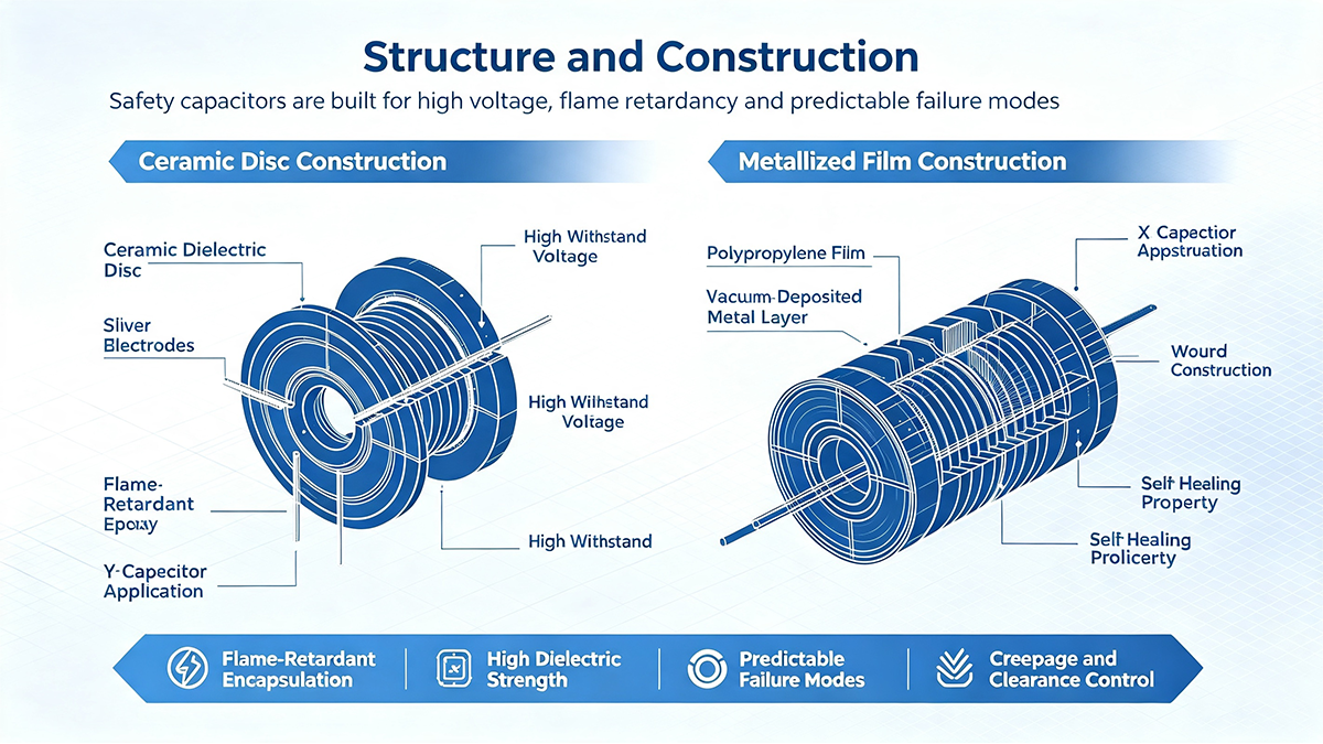
Ceramic disc safety capacitors are the most common type for Y-class applications. They consist of a ceramic dielectric disc with silver electrodes applied to both sides, encapsulated in a flame-retardant epoxy coating. The ceramic material provides excellent high-frequency characteristics and high voltage withstand capability.
2.2. Metallized Film Construction
Metallized film capacitors-typically using polypropylene film-are commonly used for X-class applications, particularly where larger capacitance values are required. A thin metal layer is vacuum-deposited onto the film, and the wound or stacked construction provides self-healing properties: if a dielectric breakdown occurs, the metallization around the fault vaporizes, clearing the short and allowing the capacitor to continue functioning.
2.3. Safety-Critical Design Features
Safety capacitors incorporate several design features that distinguish them from standard capacitors:
- Flame-retardant encapsulation to prevent fire propagation in the event of failure
- High dielectric strength to withstand voltage transients and surges on the AC mains
- Predictable failure modes-X capacitors designed to fail short, Y capacitors designed to fail open
- Creepage and clearance distances that meet safety agency requirements for insulation coordination
3. Classification per IEC 60384-14
The international standard IEC 60384-14 defines the classification, performance requirements, and test methods for fixed capacitors used in equipment connected to AC mains. Both X and Y capacitors are divided into subclasses based on their rated voltage and the impulse voltage they must survive.
3.1. X Capacitor Classes
X capacitors are classified by the peak impulse voltage they can withstand, which corresponds to the severity of the electrical environment in which they are used.
| Class | Peak Impulse Voltage | Typical Application Environment |
|---|---|---|
| X1 | 2.5 kV to 4 kV | High impulse environments, industrial applications |
| X2 | ≤ 2.5 kV | General-purpose, most consumer equipment |
| X3 | ≤ 1.2 kV | Low impulse environments |
Class X2 capacitors are the most commonly used in consumer electronics and general-purpose applications.
3.2. Y Capacitor Classes
Y capacitors are classified by their rated voltage and the peak test voltage they must withstand. The classification reflects the level of insulation required and the potential shock hazard if the capacitor fails.
| Class | Rated Voltage | Peak Test Voltage | Insulation Type |
|---|---|---|---|
| Y1 | Up to 500 V AC | 8 kV | Double or reinforced insulation |
| Y2 | Up to 300 V AC | 5 kV | Basic or supplementary insulation |
| Y4 | Up to 150 V AC | 2.5 kV | Basic insulation |
Class Y1 capacitors offer the highest level of safety and are used in applications where failure could create a shock hazard, such as across reinforced insulation. Class Y2 capacitors are the most common type used in consumer equipment.
4. Core Functions in Circuits
To fully appreciate the role of safety capacitors, it is worth understanding the broader question: what is the purpose of a capacitor in a circuit? Capacitors serve multiple fundamental functions in electronic circuits: they store electrical energy, block DC while passing AC, filter noise, smooth voltage ripples, and provide local energy storage for transient current demands.
In the context of EMI suppression, safety capacitors leverage these fundamental properties to achieve two specific goals:
4.1. Differential-Mode Noise Suppression (X Capacitors)
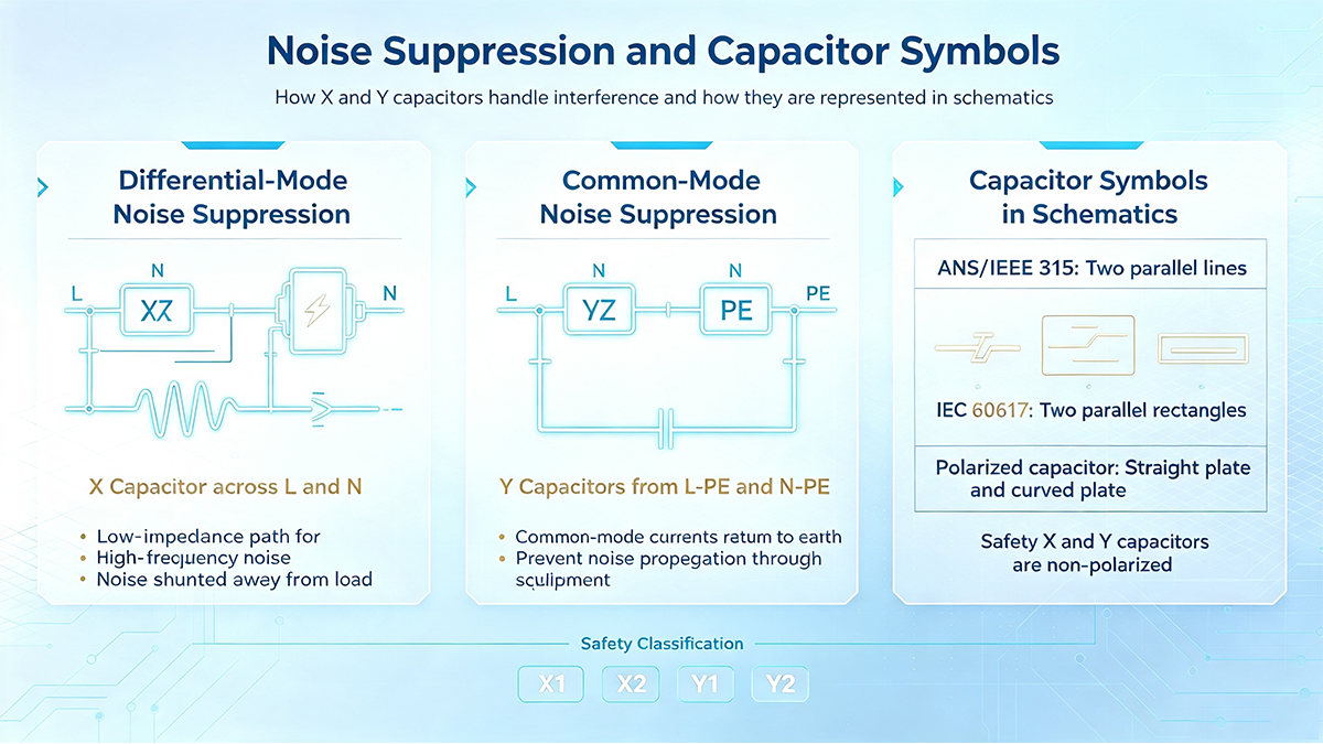
Differential-mode noise appears as a voltage difference between the line and neutral conductors. X capacitors, connected directly across L and N, provide a low-impedance path for high-frequency noise currents, shunting them away from the load. The capacitor's impedance decreases with frequency, making it effective at attenuating high-frequency differential-mode interference.
4.2. Common-Mode Noise Suppression (Y Capacitors)
Common-mode noise appears equally on both line and neutral conductors relative to earth ground. Y capacitors, connected from line-to-earth and neutral-to-earth, provide a low-impedance path for common-mode currents to return to earth, preventing them from propagating through the equipment.
4.3. The Capacitor Symbol in Schematics
When designing circuits that incorporate safety capacitors, engineers must correctly interpret and use capacitor symbols. The question what is the symbol of capacitor has a straightforward answer that varies by standard. Under the ANSI/IEEE 315 standard (common in North America), a non-polarized capacitor is drawn as two parallel lines perpendicular to the leads. Under the IEC 60617 standard (common in Europe and internationally), a non-polarized capacitor is drawn as two parallel rectangles-often called the "box" style. Polarized capacitors (electrolytic types) are represented with one straight plate (positive) and one curved plate (negative) in both standards. Safety X and Y capacitors are non-polarized and are typically drawn using the standard two-parallel-line or two-parallel-rectangle symbol, often with a note indicating their safety classification (X1, X2, Y1, Y2, etc.).
5. EMC Application Design
Safety X and Y capacitors are essential components in AC line EMI filters. Proper selection and placement are critical to achieving regulatory compliance and reliable system operation.
5.1. Typical EMI Filter Topology
A standard AC line EMI filter consists of a balanced combination of X capacitors, Y capacitors, and common-mode chokes:
- X capacitors are placed across the line and neutral-typically one before the common-mode choke (to suppress incoming differential-mode noise) and one after (to suppress noise generated by the equipment itself).
- Y capacitors are placed from line-to-earth and neutral-to-earth-typically after the common-mode choke, providing a low-impedance return path for common-mode currents.
- Common-mode chokes present high impedance to common-mode currents, while allowing differential-mode currents to pass through with minimal attenuation.
This combination creates a balanced filter that attenuates both differential-mode and common-mode EMI across a wide frequency range.
5.2. Capacitor Selection Criteria
Selecting the correct safety capacitor requires careful consideration of several parameters:
- Capacitance value: Determines the filter's corner frequency. Larger capacitance provides more attenuation at lower frequencies but increases leakage current (particularly important for Y capacitors).
- Voltage rating: Must exceed the maximum AC mains voltage with adequate margin. X capacitors are rated for AC voltage (e.g., 250 V AC, 275 V AC, 310 V AC); Y capacitors are rated for AC voltage and must meet the appropriate insulation class.
- Safety class: Must match the application's insulation requirements and impulse environment (X1/X2/X3, Y1/Y2/Y4).
- Resonant frequency: The capacitor's self-resonant frequency (SRF) determines the frequency range over which it provides effective filtering. For high-frequency noise suppression, select capacitors with SRF above the noise frequencies of interest.
- Equivalent series resistance (ESR) and equivalent series inductance (ESL): Lower ESR and ESL improve high-frequency performance. Surface-mount capacitors with optimized geometries can significantly reduce ESL.
5.3. PCB Layout Considerations
Proper PCB layout is essential for maximizing the effectiveness of safety capacitors in EMI filtering:
- Place capacitors as close as possible to the noise source or the point of entry to minimize the loop area and parasitic inductance.
- Use short, wide traces for the capacitor connections to reduce series inductance.
- Minimize the distance between the capacitor and the earth ground connection for Y capacitors to provide the lowest impedance return path.
- Avoid placing Y capacitors near sensitive analog circuits to prevent leakage currents from introducing noise.
- Consider using multiple capacitors in parallel to achieve a lower impedance across a wider frequency range. A large capacitor provides low-frequency filtering, while a smaller capacitor in parallel provides high-frequency filtering.
6. Motor Run Capacitors and Safety Capacitors: A Comparison
While this article focuses on safety X and Y capacitors, it is useful to understand how they relate to other capacitor types. The question what does a motor run capacitor do is a common one in AC power applications.
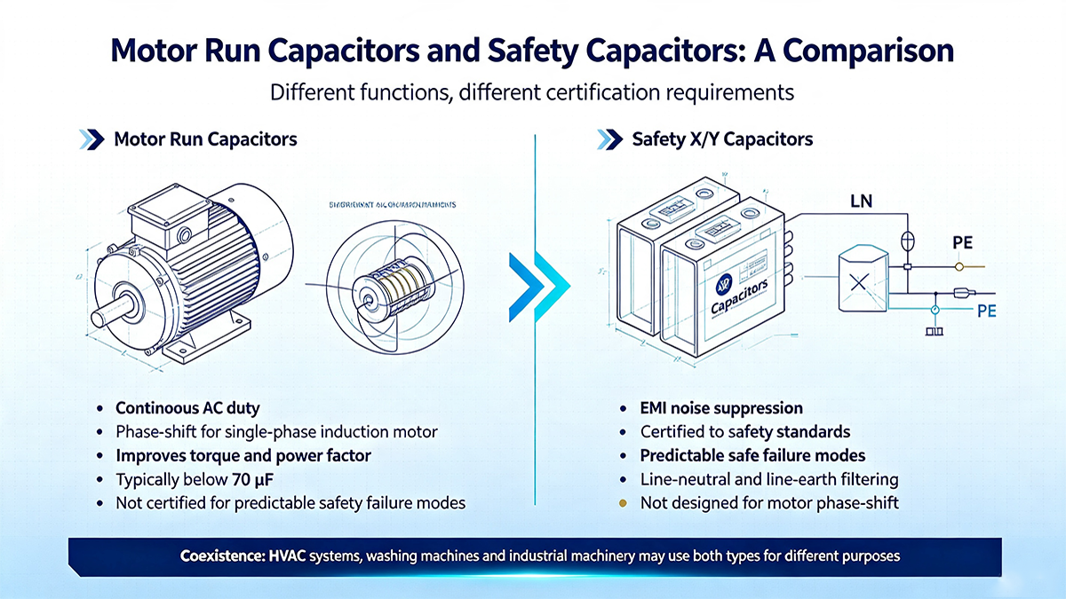
A motor run capacitor is an AC capacitor designed for continuous operation in single-phase induction motors. It remains connected to the auxiliary winding at all times, creating a phase shift that produces a rotating magnetic field-enabling the motor to start and run efficiently. Motor run capacitors improve running torque and efficiency by maintaining the rotational field under optimum conditions, and they can improve the power factor up to nearly unity when properly selected. They are rated for continuous duty and typically have capacitance values below 70 µF.
By contrast, safety X and Y capacitors are not designed for motor phase-shift applications. They are specialized for EMI suppression and are certified to meet safety standards that motor run capacitors do not necessarily satisfy. The key distinction is the failure mode requirement: motor run capacitors are not required to fail in a predictable, safe manner for personnel protection, whereas safety capacitors are.
In some motor-driven equipment-such as HVAC systems, washing machines, and industrial machinery-both motor run capacitors (for motor operation) and safety capacitors (for EMI filtering) may be present in the same product, serving entirely different purposes.
7. Capacitors in Constant Current Regulators
Another important application of capacitors-distinct from EMI filtering-is in constant current regulators. The role of a capacitor in a constant current regulator depends on the regulator topology and the specific design goals.
In switching constant current regulators (such as those used for LED driving), capacitors play several critical roles:
- Input capacitors filter rectified AC and provide a stable DC bus for the regulator.
- Output capacitors smooth the switching ripple and provide a stable current to the load. In some designs, the output capacitor is essential for correct feedback operation, as it holds the voltage up long enough for the control loop to respond.
- Bypass capacitors close to the regulator IC provide local energy storage for high-frequency switching transients.
However, the use of output capacitors in constant current regulators is not universal. Some designs intentionally omit the output capacitor because a theoretically ideal current source has infinite output impedance, whereas a capacitor would reduce that impedance at high frequencies. The decision to include or omit an output capacitor depends on the specific regulator topology, the load characteristics, and the desired transient response.
Importantly, safety X and Y capacitors are not typically used in constant current regulator applications unless the regulator is directly connected to the AC mains and requires EMI filtering at the input. In that case, X capacitors would be placed across the AC input lines, and Y capacitors would be placed from the AC lines to earth ground-exactly as in any other AC-powered equipment.
8. Common Failures and Design Pitfalls
Despite their robust design, safety capacitors can fail-and when they do, the consequences can be serious. Understanding common failure modes helps engineers design more reliable systems.
- Overvoltage stress: Voltage transients exceeding the capacitor's impulse rating can cause dielectric breakdown. For X capacitors, this should result in a short circuit that clears the fuse; for Y capacitors, the capacitor must fail open.
- Aging and capacitance degradation: Over time, the capacitance of safety capacitors can decrease due to dielectric aging and environmental factors. This reduces filtering effectiveness and may lead to EMI compliance failures.
- Incorrect classification: Using an X2 capacitor in an application that requires X1 (high impulse environment) can lead to premature failure. Using a Y2 capacitor where Y1 is required (across reinforced insulation) creates a potential shock hazard.
- Leakage current in Y capacitors: Y capacitors inherently pass a small AC leakage current to earth. In medical or other low-leakage applications, this must be carefully managed.
- Parasitic inductance: The equivalent series inductance (ESL) of safety capacitors can limit their high-frequency performance, particularly for surface-mount types. In some designs, the ESL of the X-capacitor can limit effectiveness up to 40 MHz.
9. Safety Capacitor Design Checklist
- Identify the required X capacitor class (X1, X2, X3) based on the impulse environment.
- Identify the required Y capacitor class (Y1, Y2, Y4) based on the insulation requirements.
- Select capacitance values that achieve the desired EMI filter corner frequency.
- Verify that the capacitor's voltage rating exceeds the maximum AC mains voltage.
- Confirm safety agency certification (UL, CSA, VDE, IEC).
- Place X capacitors across line and neutral (L–N) for differential-mode suppression.
- Place Y capacitors from line-to-earth and neutral-to-earth (L–E, N–E) for common-mode suppression.
- Minimize trace lengths and loop areas to reduce parasitic inductance.
- Consider using multiple parallel capacitors for wider frequency coverage.
- Verify that Y capacitor leakage current meets the application's safety requirements.
10. Frequently Asked Questions (FAQ)
X capacitors are connected across line and neutral (L–N) and suppress differential-mode noise. They must fail short to clear the fuse. Y capacitors are connected from line-to-earth and neutral-to-earth (L–E, N–E) and suppress common-mode noise. They must fail open to avoid shock hazards.
A motor run capacitor creates a phase shift in single-phase induction motors, producing a rotating magnetic field that enables the motor to start and run efficiently. It is designed for continuous duty and improves running torque and power factor. Safety capacitors, by contrast, are designed for EMI suppression and are certified to meet safety standards for AC mains connection-including predictable failure modes that motor run capacitors do not require.
Under ANSI/IEEE 315 (North America), a non-polarized capacitor is drawn as two parallel lines. Under IEC 60617 (international), it is drawn as two parallel rectangles ("box" style). Polarized capacitors are drawn with one straight plate (positive) and one curved plate (negative). Safety X and Y capacitors are non-polarized and typically use the standard symbol with a note indicating their safety classification.
Capacitors serve multiple purposes in circuits-energy storage, filtering, decoupling, and smoothing. In EMI filtering, X capacitors provide a low-impedance path for differential-mode noise across L and N, while Y capacitors provide a low-impedance path for common-mode noise to earth.
In switching constant current regulators, input capacitors filter the AC input, output capacitors smooth switching ripple and stabilize the feedback loop, and bypass capacitors provide local high-frequency energy storage. However, some designs omit output capacitors because an ideal current source has infinite output impedance, and a capacitor would reduce that impedance.
11. Industry Development Trends
The safety capacitor market continues to evolve in response to new regulatory requirements, higher power densities, and emerging applications. Current trends include:
- Miniaturization: Surface-mount safety capacitors in smaller packages (e.g., 1808, 2220) enable higher-density PCB designs without compromising safety ratings.
- Higher voltage ratings: As electric vehicles and industrial equipment operate at higher voltages, safety capacitors with higher AC and impulse ratings are being developed.
- AEC-Q200 qualification: Automotive-grade safety capacitors are now available, meeting the rigorous reliability requirements of the automotive industry.
- Integrated EMI filtering: Research into active X-Y capacitors and hybrid EMI filters aims to reduce the size and weight of passive EMI filters, particularly for high-power converters.
- Improved high-frequency performance: Advances in capacitor construction are reducing ESL, enabling effective EMI suppression at higher frequencies.
Despite these trends, the fundamental safety requirements of IEC 60384-14 remain unchanged-ensuring that X capacitors fail short and Y capacitors fail open, protecting both equipment and personnel.
12. Conclusion
Safety X and Y capacitors are indispensable components in AC-powered electronic equipment, providing essential EMI suppression while meeting rigorous safety requirements. Understanding their structure, classification per IEC 60384-14, and proper application in EMI filter design is fundamental to achieving regulatory compliance and reliable system operation.
By carefully selecting the appropriate X and Y classes, placing capacitors correctly in the circuit, and following best practices for PCB layout, engineers can effectively suppress both differential-mode and common-mode EMI-ensuring that their designs meet EMC requirements without compromising safety.
This article was prepared by the hsyic Technology Team based on widely accepted engineering practices and safety capacitor manufacturer specifications. It is brand-neutral and intended for educational reference. Always consult the specific datasheet of the safety capacitor you are using for precise parameters and derating curves, and verify that the component carries the required safety agency certification (UL, CSA, VDE, IEC) for your application. For critical designs, perform thorough EMI pre-compliance testing under actual operating conditions.
-- hsyic Technology Team