
1. Working Principle and Temperature Characteristics
NTC thermistors are sintered from composite metal-oxide semiconductor materials (e.g., manganese, nickel, and cobalt oxides). As temperature rises, the internal carrier density increases, leading to a continuous decrease in resistance. The resistance–temperature (R–T) curve exhibits a strong nonlinear negative correlation.
- High Sensitivity: Small temperature changes cause significant resistance variations-far more sensitive than linear resistive sensors (e.g., RTDs). Typical sensitivity is about −3% to −5% per °C.
- Negative Coefficient: Resistance decreases exponentially with rising temperature. This forms the core detection principle for thermal circuits.
- Fast Thermal Response: The small chip volume enables rapid temperature tracking for real-time heat monitoring (response time typically < 10 seconds in still air).
-
Nonlinear Curve: The R–T relationship is not linear; accurate temperature extraction requires a lookup table or the Steinhart–Hart equation:
1/T = A + B·ln(R) + C·(ln(R))³, where A, B, and C are material-specific constants.
2. NTC Classification and Typical Applications
NTC thermistors are broadly divided into temperature measurement types and power inrush-current limiting types. Their internal construction and specifications differ significantly.
| Type | Key Characteristics | Typical Applications |
|---|---|---|
| Precision Measurement NTC | High accuracy (1%~3% tolerance), stable B-value, small size | Battery temperature monitoring, PCB thermal sensing, HVAC, medical devices |
| Power Inrush-Current Limiting NTC | High initial resistance (e.g., 5Ω~50Ω at 25°C), handles high surge current | AC/DC power supplies, motor start-up circuits, capacitor pre-charge |
| High-Temperature Waterproof NTC | Sealed epoxy or glass encapsulation, rated up to 300°C | Water heaters, industrial ovens, exhaust gas monitoring |
| Miniature SMD NTC | Ultra‑small footprint (e.g., 0402, 0603), fast response | Wearables, smartphone battery packs, compact modules, MCU die temperature sensing |
Selecting the right type depends on the required temperature range, accuracy, response time, and power dissipation capability. For most general-purpose embedded designs, the precision measurement NTC with R25 = 10kΩ and B25/85 ≈ 3435K is a common choice.
3. Key Electrical Parameters for Selection
Four core parameters determine the detection accuracy and operational reliability of an NTC:
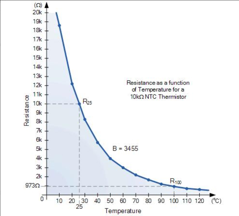
- R25 (Nominal Resistance at 25°C): The standard resistance value at room temperature (25°C). Common values are 1kΩ, 2kΩ, 10kΩ, and 100kΩ. It determines the matching range of the voltage-divider circuit and directly affects the ADC input voltage swing.
- B‑value (Material Constant): Reflects temperature sensitivity. A higher B‑value (e.g., 3950K vs. 3435K) means a larger resistance change per °C, providing higher sensitivity but also a narrower usable range. The B‑value is typically specified between 25°C and 85°C (B25/85) or 25°C and 50°C.
- Tolerance: Specifies the resistance tolerance at 25°C (e.g., ±1%, ±3%, ±5%) and B‑value tolerance (±1% ~ ±5%). For precision measurements, select 1% R‑tolerance and 1% B‑tolerance.
- Maximum Power Rating (Pmax): The maximum continuous power the NTC can dissipate without self‑heating causing measurement errors. Typically ranges from 0.1W to 1W. Exceeding this leads to self‑heating drift.
Additionally, the dissipation factor (δ, mW/°C) indicates how much power is needed to raise the NTC's temperature by 1°C. A lower δ is preferable for measurement accuracy (less self‑heating).
4. Comparison: NTC vs. RTD vs. Thermocouple vs. Digital IC
| Sensor Type | Accuracy | Temperature Range | Cost | Complexity | Best Use Case |
|---|---|---|---|---|---|
| NTC Thermistor | ±0.5°C ~ ±2°C | −40°C ~ +150°C | Low | Moderate (nonlinear) | Embedded, battery, consumer |
| RTD (Pt100) | ±0.1°C ~ ±0.5°C | −200°C ~ +850°C | High | High (needs current source) | Industrial, precision lab |
| Thermocouple | ±1°C ~ ±5°C | −200°C ~ +2000°C | Low | High (cold‑junction compensation) | High‑temperature furnaces |
| Digital IC (e.g., LM75) | ±0.5°C ~ ±1°C | −55°C ~ +125°C | Medium | Low (I²C/SPI) | System thermal management |
NTC thermistors strike an excellent balance between cost, sensitivity, and size, making them the preferred choice for most battery‑powered and space‑constrained applications where extreme precision is not required.
5. Standard Temperature Sampling Circuit Design
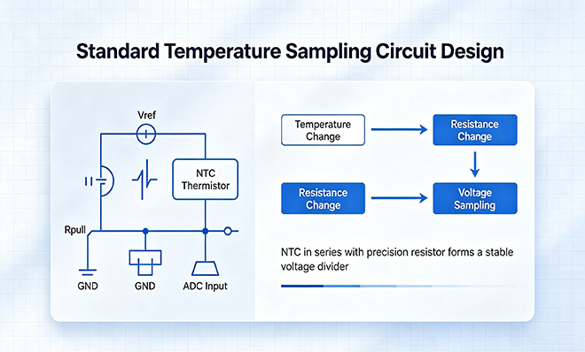
The most common and stable topology for NTC measurement is the voltage divider circuit. The NTC is placed in series with a fixed precision resistor (Rpull) between a stable reference voltage (Vref) and ground, and the junction voltage is fed to an ADC input.
5.1. Divider Configuration
- Top‑side NTC configuration: NTC between Vref and the ADC pin, with the fixed resistor to ground. The output voltage decreases as temperature rises.
- Bottom‑side NTC configuration: Fixed resistor to Vref, NTC to ground. The output voltage increases as temperature rises.
The choice depends on the ADC input range and the desired monotonic behavior. For most MCUs with a 3.3V reference, a 10kΩ NTC with a 10kΩ pull‑up resistor is a standard combination.
5.2. Calculating the Divider Resistor
The pull‑up resistor should be chosen to maximize the voltage swing across the temperature range of interest. A common rule is to set Rpull ≈ RNTC at the midpoint of the temperature range. For example, if measuring 25°C~85°C with R25=10kΩ and R85≈2kΩ, a 4.7kΩ~10kΩ resistor is appropriate.
5.3. Low Self‑Heating Design
The power dissipated in the NTC should be kept below 1/10 of Pmax to limit self‑heating. Calculate: P = Vref² / (Rpull + RNTC)² · RNTC. For Vref=3.3V, Rpull=10k, and RNTC=10k, P ≈ 0.27mW, which is generally safe for most NTCs (Pmax is typically 100mW).
5.4. RC Filter for Noise Suppression
Add a low‑pass RC filter (e.g., a 1kΩ resistor and a 0.1µF capacitor) at the ADC input to attenuate high‑frequency noise and stabilize the readings. The corner frequency fc = 1/(2πRC) should be well below the sampling frequency.
5.5. Software Nonlinear Calibration
Since the ADC output is proportional to voltage, which is nonlinearly related to temperature, the firmware must convert the ADC code to resistance, and then to temperature using either a precomputed lookup table (with interpolation) or the Steinhart–Hart equation. For most applications, a 16‑point lookup table with linear interpolation provides sufficient accuracy.
6. PCB Layout Guidelines
Proper PCB layout ensures that the NTC accurately tracks the actual ambient or component temperature, rather than measuring its own self‑heating or external thermal interference.
- Placement close to the heat source: Position the NTC near the target component (e.g., MOSFET, power inductor, battery cell) to monitor the hot spot directly. Use thermal vias or copper planes for better heat conduction if necessary.
- Avoid external thermal interference: Keep the NTC away from high‑current traces, voltage regulators, and other heat‑generating components that are not the measurement target. Also avoid placing it above large ground planes that may sink heat unevenly.
- Isolate from airflow and cooling holes: If the PCB is in an enclosure with forced airflow, position the NTC so it is not directly exposed to cooling fans or vent holes, which could lower its measured temperature relative to the actual component.
- Short and shielded traces: Keep the analog signal trace from the divider to the ADC as short as possible, and route it away from digital signal lines to minimize noise coupling. A ground guard ring can be placed around the trace.
- Thermal isolation from the PCB: For surface‑mount NTCs, avoid connecting both pads to large copper planes, as this increases thermal mass and slows down the response time. One pad can be connected to a narrow trace to reduce heat sinking.
7. Common Failures and Abnormal Phenomena
Most temperature detection errors can be traced to self‑heating, inadequate calibration, or poor layout. Below are typical issues and their root causes:
- Static temperature error (bias): Caused by a lack of software calibration. The nonlinear R–T curve, combined with resistor tolerances, creates a fixed offset. Solution: perform one‑point or two‑point calibration during production.
- Self‑heating drift: When the loop current is too high, the NTC dissipates significant power and raises its own temperature, resulting in a reading higher than the actual ambient temperature. Reduce Vref or increase Rpull to limit the current.
- ADC sampling jitter: Power‑supply noise or high‑frequency interference causes unstable voltage readings. Add an RC filter and ensure proper ADC sampling timing (e.g., averaging multiple samples).
- Slow thermal response: Thick encapsulation or a long thermal path (e.g., the NTC placed far from the heat source) delays the reading. Use a smaller package or move the NTC closer.
- Over‑current burnout: In power limiting applications, repeated high surge currents can age the NTC, causing permanent resistance shift. Select a device with adequate surge energy rating for the application.
- Moisture ingress: For uncoated NTCs, humidity can affect surface resistivity, leading to measurement drift. Use conformal coating or hermetically sealed versions for humid environments.
8. Reliability Verification Test Items
To guarantee long‑term detection precision, the following tests should be performed during the design validation phase:
- Constant temperature bath calibration: Immerse the NTC in a stirred temperature bath at three points (e.g., 0°C, 25°C, 85°C) and record the ADC output. Build a calibration curve or derive the Steinhart–Hart coefficients.
- Self‑heating power test: Measure the NTC resistance at two different excitation currents (e.g., 10µA and 100µA). If the difference exceeds the equivalent of 0.5°C, reduce the excitation current.
- Temperature cycling aging test: Subject the NTC to multiple cycles of −40°C ↔ +125°C (e.g., 100 cycles) and check for resistance drift. This screens for mechanical stress failures.
- Long‑term thermal stability test: Operate the NTC continuously at its maximum rated temperature for 1000 hours and monitor resistance drift. Drift should remain within the tolerance specification.
- Humidity exposure test: Expose the NTC to 85°C/85%RH for 168 hours and measure the resistance change. For non‑sealed types, a drift of >3% indicates poor moisture resistance.
9. NTC Temperature Sensing Design Checklist
- Select R25 based on the ADC input range and the desired voltage swing.
- Choose the B‑value and tolerance according to the required temperature accuracy.
- Calculate the divider resistor to optimize sensitivity over the target temperature range.
- Verify that the self‑heating power is < 1/10 of Pmax.
- Add an RC filter (R≈1kΩ, C≈0.1µF) at the ADC input.
- Place the NTC close to the heat source, avoiding airflow and copper pours.
- Keep the analog trace short and away from digital signals.
- Implement firmware using either a lookup table or the Steinhart–Hart equation.
- Perform at least a two‑point calibration during production.
- Validate the thermal response time and stability with environmental tests.
10. Frequently Asked Questions (FAQ)
The exponential behavior is inherent to the semiconductor material. While you can use a parallel resistor to linearize the response over a narrow range, this reduces sensitivity. The preferred method is to use a software lookup table or polynomial interpolation.
The B‑value is calculated from the resistance at two temperatures. B25/85 uses 25°C and 85°C, which is the most common specification. B25/50 uses 25°C and 50°C. The B‑value is slightly temperature‑dependent; using the wrong temperature pair can introduce errors. Always use the B‑value specified for your target temperature range.
Yes, but you must choose the pull‑up resistor appropriately. For a 10kΩ NTC, a 10kΩ pull‑up gives an output voltage range from about 1.65V (at 25°C) to 0.5V (at high temperature). Ensure this range fits within your ADC's input range. Using a precision voltage reference can further improve accuracy.
Most NTCs are sensitive to excessive heat. Follow the recommended soldering profile (usually a peak temperature of ≤ 260°C for SMD types). For manual soldering, use a temperature‑controlled iron (≤ 350°C) and minimize the contact time.
Under normal operating conditions (within rated temperature and power), NTC thermistors have a long lifespan, typically exceeding 10 years. However, in power limiting applications where they experience repeated high surge currents, aging can occur, resulting in resistance drift. Regular calibration is recommended for critical systems.
11. Industry Development Trends
NTC thermistors remain the mainstream low‑cost temperature detection solution in consumer electronics, automotive, and industrial markets. Current trends include:
- Ultra‑high precision and consistency: Manufacturers are improving material uniformity to achieve B‑value tolerances of ±0.5% and R‑tolerances of ±0.5%, reducing the need for individual calibration.
- Miniaturization: SMD packages as small as 0201 (0.6mm × 0.3mm) enable integration into wearable and implantable devices.
- Enhanced linearization: Some new NTC materials exhibit more linear R–T curves, simplifying firmware and improving accuracy over wide ranges.
- Integrated solutions: Modules combining the NTC, filter, and ADC driver circuits are emerging to reduce external components.
- Cooperation with digital sensors: In high‑end systems, NTCs are used in conjunction with digital temperature sensors for cross‑validation and compensation.
Despite the rise of digital temperature sensors, NTC thermistors remain irreplaceable due to their low cost, high sensitivity, and flexibility. By following sound design practices-proper resistor matching, self‑heating avoidance, and nonlinear calibration-engineers can achieve accurate and stable temperature monitoring for a wide range of applications.
12. Conclusion
NTC thermistors provide a cost‑effective, highly sensitive solution for temperature sensing in modern electronics. Understanding their nonlinear characteristics, selecting appropriate parameters, and implementing a well‑designed voltage‑divider circuit with proper PCB layout and software calibration are essential for achieving reliable thermal management. By referencing this guide, engineers can avoid common pitfalls and optimize their designs for both accuracy and longevity.